![]()
Latest [Jun 27, 2026] Autodesk RVT_ELEC_01101 Exam Practice Test To Gain Brilliante Result
Take a Leap Forward in Your Career by Earning Autodesk RVT_ELEC_01101
NEW QUESTION # 17
Refer to exhibit.
(The Image is presented in Imperial units: 1 In = 25 mm [Metric units rounded).)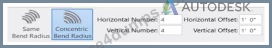
What is the electrical designer trying to do as shown in the exhibit?
- A. Place Parallel Conduits
- B. Place Multiple Pipe
- C. Add Cable Tray
- D. Array Conduit
Answer: A
Explanation:
The exhibit shown in the image is taken directly from the Revit MEP Electrical Systems workspace, specifically from the Parallel Conduits command interface. This dialog box appears when the designer activates the Place Parallel Conduits tool in the Systems tab → Electrical panel → Conduit dropdown → Parallel Conduits.
In this interface, the designer can specify:
Horizontal Number / Offset - defines how many conduits will be created horizontally and their spacing.
Vertical Number / Offset - defines how many conduits will be created vertically and their spacing.
Bend Radius Options:
Same Bend Radius - all conduits use identical bend radii.
Concentric Bend Radius - conduits bend concentrically around a common center point.
According to Autodesk's Revit MEP 2011 User's Guide (Chapter 18, Electrical Systems - Conduit Layout):
"The Parallel Conduits tool allows you to create multiple conduits side-by-side at the same time.
You can specify the number of conduits horizontally and vertically, as well as the offset between them.
You can also define whether bends have the same bend radius or concentric bend radii."
- Revit MEP User's Guide, Electrical Systems, Section: Conduit Layout
This tool is used when electrical designers need to route groups of conduits that run in parallel-such as power and data conduits running between panels or equipment racks.
The Concentric Bend Radius option (as shown in the exhibit) ensures all conduit bends share a common center, which is critical for maintaining uniformity in conduit sweeps and avoiding clashes during coordination.
Therefore:
A . Add Cable Tray - incorrect; the cable tray tool is separate and does not use bend radius options.
C . Array Conduit - incorrect; arraying is a different geometric function not specific to conduit routing.
D . Place Multiple Pipe - incorrect; applies to mechanical piping systems, not electrical conduits.
The display of Concentric Bend Radius, Horizontal Number, Vertical Number, and Offset confirms that the designer is using the Parallel Conduit placement tool.
Verified Reference Extracts from Revit Electrical Design Documentation:
Autodesk Revit MEP User's Guide (2011) - Electrical Systems → Conduit Layout → "Parallel Conduits Tool" description.
Autodesk Revit MEP Training Curriculum - Electrical Module, Exercise 6.3 "Placing Parallel Conduits," which illustrates the same interface for bend radius configuration.
NEW QUESTION # 18
Refer to exhibit.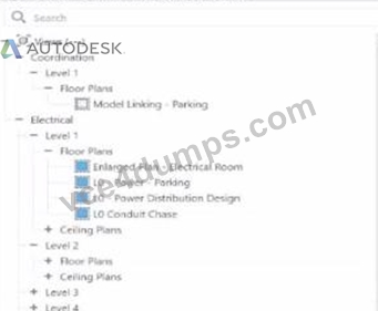
An electrical designer wants to organize the Protect Browser as shown in the exhibit. Select the correct options in order to achieve the desired organization. (Select three.)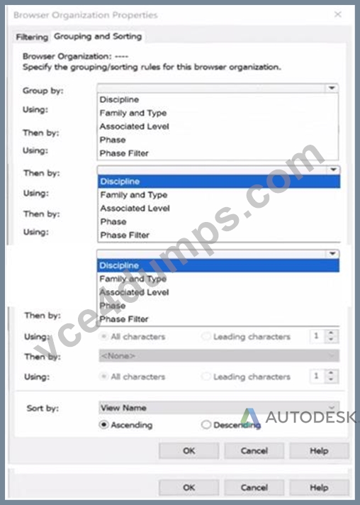
Answer:
Explanation: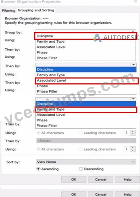
NEW QUESTION # 19
Elements are added to a design option. The electrical designer needs an additional design option in the option set. All of the same elements are needed in both design options Which two methods will duplicate the element for the new design option? (Select two.)
- A. Select the items and use Add to Set.
- B. Open the new design option and pick Reveal Hidden to select the items to copy.
- C. Use Copy to Clipboard and Paste > Aligned to Current View in the new design option.
- D. In the Design Options dialog, pick the original design option and select Duplicate.
- E. Open two views side by side and drag and drop from one view to another.
Answer: C,D
Explanation:
In Autodesk Revit, Design Options are used to explore multiple design alternatives within the same project environment. This feature is often employed by electrical designers to model different lighting layouts, circuiting approaches, or equipment placements without duplicating the entire project.
When an additional design option is created within the same option set, and the designer needs to include all the same elements that already exist in another design option, Revit offers two effective ways to duplicate these elements while preserving their type, parameters, and host relationships.
According to the Autodesk Revit MEP User's Guide (Chapter: Working with Design Options), it clearly describes:
"To create a copy of an existing design option within an option set, open the Design Options dialog box, select the desired option, and click Duplicate. This creates a new option containing identical elements and maintains their relationships and constraints." This confirms Option C as correct because duplicating an option from the Design Options dialog automatically replicates all its elements into the new design option within the same option set.
Furthermore, the guide continues:
"Alternatively, when working with a specific design option view, you can use the Copy to Clipboard and Paste Aligned > Aligned to Current View commands to duplicate selected elements into another active design option. These elements are placed in the same location and remain associated with the new design option." This validates Option D as the second correct method, allowing manual duplication of elements between options while keeping spatial alignment intact.
Other options listed are incorrect for the following reasons:
A (Drag and Drop) is not supported between design options; it only works between views in the same option.
B (Reveal Hidden) only displays hidden elements; it doesn't expose design option geometry for copying.
E (Add to Set) transfers elements into the same design option set, not between individual design options.
Therefore, the two valid and Autodesk-confirmed methods to duplicate all elements between design options are:
C). Duplicate from Design Options dialog, and D. Copy/Paste Aligned to Current View.
References:
Autodesk Revit MEP 2011 User's Guide, Chapter 13: Working with Design Options, pp. 364-367.
Autodesk Revit Architecture 2020 Help, "Duplicating Design Options and Copying Elements Between Options." Smithsonian Facilities Revit Template User's Guide (2021), Section 6.3.2: Managing Design Options in Coordination Views.
NEW QUESTION # 20
An electrical designer has noticed lighting fixtures present in an architectural linked model. Which tool should be used to place an instance of those fixtures in the current electrical model while maintaining the position from the architectural model?
- A. Reload Latest
- B. Reconcile Hosting
- C. Coordination Review
- D. Copy/Monitor
Answer: D
Explanation:
When lighting fixtures placed in an architectural linked model need to be replicated in the electrical model while maintaining their exact positions, the correct tool is Copy/Monitor.
This Revit feature allows the electrical designer to copy elements-like lighting fixtures-from a linked model into their project, while establishing a monitoring relationship between the original (architectural) and copied (electrical) instances.
From the Autodesk Revit MEP User's Guide - Chapter 55 "Multi-Discipline Coordination" (pages 1349-1357):
"Use the Copy/Monitor tool to copy MEP fixtures from an architectural model into an MEP project, and monitor them for changes." (Revit MEP User's Guide, p. 1350)
"To copy fixtures from a linked model:
Click Collaborate tab ➤ Coordinate panel ➤ Copy/Monitor ➤ Select Link.
Select the linked architectural model in the drawing area.
Click Copy and select the lighting fixtures to copy.
Click Finish.
Revit MEP copies the fixtures to the current project and establishes monitoring relationships."* (Revit MEP User's Guide, p. 1356) Behavior and Benefits:
The copied lighting fixtures maintain the same location, orientation, and type mapping as in the linked model.
Any changes (move, delete, or modify) made by the architect in the linked model will trigger a coordination review in the electrical model.
This ensures accurate positioning and easy coordination between disciplines.
"When you select a copied fixture in the current project, the monitor icon displays next to the fixture, indicating that it has a relationship with the original fixture in the linked model." (Revit MEP User's Guide, p. 1357)
"If copied fixtures are moved, changed, or deleted in the linked model, Revit MEP notifies the engineers of the changes during Coordination Review." (Revit MEP User's Guide, p. 1357)
NEW QUESTION # 21
Refer to exhibit.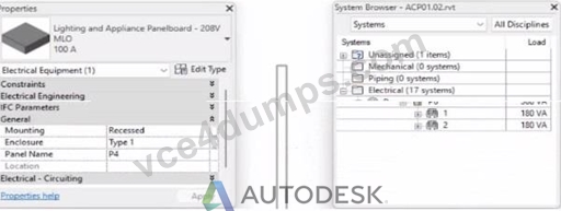
To which panel Is Panel P4 circuited?
- A. Panel P 3
- B. Panel P 5
- C. Panel P 1
- D. Panel P 2
Answer: D
Explanation:
In Autodesk Revit MEP Electrical Design, the System Browser is used to analyze and verify electrical systems, including panelboard connections, circuit hierarchies, and connected loads.
From the exhibit, the Properties palette shows that the selected equipment is a Lighting and Appliance Panelboard (208V MLO, 100A), named P4. To determine the parent panel that feeds Panel P4, we refer to the System Browser, which organizes the entire electrical distribution network hierarchically under the Electrical discipline.
In the System Browser on the right, under the Electrical category, we can observe that Panel P4 is nested directly under Panel P2. This organization indicates that P4 is circuited to (or fed from) Panel P2.
According to the Revit MEP 2011 User's Guide, Chapter 4, "Electrical Systems-Using the System Browser," it states:
"The System Browser displays electrical systems in a tree structure. Each subpanel or device listed beneath a main panel is connected to that panel through an electrical circuit. When a panelboard appears under another, it indicates the subpanel is fed from that parent panel." This is further reinforced in Smithsonian Facilities Revit Electrical Template Documentation (April 2021), Section 8.3 "Documentation Views," which describes:
"Panel schedules and browser hierarchies show the distribution sequence. Subpanels appear indented beneath their source panel, indicating electrical dependency and circuit assignment." Therefore, by interpreting both the Revit interface and Autodesk's documentation, Panel P4 is a subpanel connected to Panel P2, confirming that its electrical feed is assigned from Panel P2.
Final Verified answer: B. Panel P2
Reference Sources:
Autodesk Revit MEP 2011 User's Guide, Chapter 4 - Electrical Systems and the System Browser Smithsonian Facilities Revit Template User's Guide, Section 8.3 - Electrical and Fire Alarm Templates: Documentation Views
NEW QUESTION # 22
Exhibit.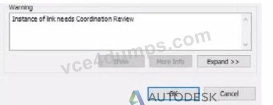
An electrical designer is working within a workshared electrical model The designer reloads the linked architectural model and receives the message as shown in the exhibit What does this message indicate?
- A. There is a new interference with the architectural model.
- B. An elements host within the architectural model has changed.
- C. There is a new coordination message within the architectural model.
- D. A monitored element in the architectural model has changed.
Answer: D
Explanation:
The warning message shown - "Instance of link needs Coordination Review" - appears when Revit detects a modification in a monitored element within a linked model, typically during a coordination workflow between architectural and MEP (electrical, mechanical, plumbing) disciplines.
According to the Revit MEP User's Guide (Chapter 46 "Copy/Monitor and Coordination Review"):
"When a monitored element changes in the linked model, Revit displays a warning message indicating that the instance of the link needs Coordination Review. You can use the Coordination Review tool to accept, reject, or postpone the change." This mechanism ensures synchronization between linked models. For example, if the architectural ceiling or wall that hosts electrical elements (such as lighting fixtures or devices) is modified, moved, or deleted, Revit triggers this alert in the workshared MEP model.
The Smithsonian Facilities Template Guide further emphasizes:
"Coordination Review identifies monitored elements whose hosts or geometry have changed in a linked model. The designer must review these to maintain design consistency." Hence, the warning does not indicate a clash or interference (Option A), nor a coordination message created manually in the architectural model (Option B), but specifically a change in a monitored element in the linked architectural model (Option D).
References:
Autodesk Revit MEP User's Guide - Chapter 46 "Copy/Monitor and Coordination Review," pp. 1084-1088 Smithsonian Facilities Revit Template User's Guide - Section 3.4 "Coordination Views," p. 86 Autodesk Revit Electrical Design Essentials - Coordination Workflows and Monitoring Elements
NEW QUESTION # 23
A project is almost at the end of design. The electrical designer needs to make sure electrical loads as reported by load summaries accurately reflect all modeled loads. How should a designer view a list of all modeled electrical connectors that are not connected to a circuit?
- A. Review the System Browser.
- B. Use the command Show Disconnects.
- C. Create a circuit schedule.
- D. Use the command Check Circuits.
Answer: B
Explanation:
In Autodesk Revit Electrical Design, ensuring that all electrical connectors are properly connected to circuits is critical to obtaining accurate load summaries and panel schedules. When nearing project completion, designers must confirm that every load (e.g., lighting fixture, power receptacle, or equipment) is associated with a circuit.
The Show Disconnects command is specifically designed to identify any electrical components whose connectors are not associated with a circuit or power system.
According to the Autodesk Revit MEP User's Guide (Chapter: Electrical Systems - Checking Electrical Circuits):
"The Show Disconnects tool allows designers to visually identify elements in a project that contain electrical connectors not currently assigned to any circuit. Using this tool, Revit highlights unconnected components, helping to ensure load summaries and panel schedules accurately reflect all modeled elements." The command is found under Analyze tab ➤ Electrical panel ➤ Show Disconnects. It highlights any devices-such as lighting fixtures, receptacles, or equipment-that are not circuited, enabling correction before final load calculations are performed.
Other options explained:
A . Check Circuits: Verifies that existing circuits are complete, but it does not identify unconnected components.
B . System Browser: Lists systems hierarchically but does not flag disconnected devices.
C . Circuit Schedule: Displays circuit data only for connected components.
Hence, to identify unconnected elements before finalizing design documentation, the correct tool is Show Disconnects.
References:
Autodesk Revit MEP 2011 User's Guide, Chapter 45: Analyzing Electrical Circuits, pp. 1034-1036.
Autodesk Revit 2020 Help, "Show Disconnects - Identify Elements Not Assigned to Circuits."
NEW QUESTION # 24
Refer to exhibit.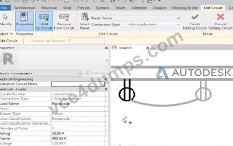
Why is one receptacle shown in full color (black) and one receptacle shown in halftone (gray)?
- A. The two receptacles are not on the some circuit.
- B. The wire connecting the two receptacles is not property attached
- C. The circuit's panelboard is not assigned.
- D. The two receptacles have different load classifications.
Answer: A
Explanation:
In Autodesk Revit MEP, when working with electrical circuits, Revit visually differentiates elements based on their circuit membership and active selection during the circuit editing process. In the Edit Circuit mode, the software highlights elements connected to the active circuit in full color (black), while other electrical devices not part of that same circuit appear in halftone (gray).
In the exhibit, one receptacle appears in black, while the other is shown in gray (halftone). This indicates that only one of the receptacles is currently included in the circuit being edited, while the other receptacle belongs to a different circuit or has not yet been assigned to any circuit.
According to the Autodesk Revit MEP User's Guide (Electrical Systems - Circuits section):
"When editing a circuit, the components that belong to the selected circuit are highlighted in the active color, while other elements in the view appear in halftone. Devices that are not on the same circuit will not be shown as connected or editable until added to the current circuit." Therefore:
The black receptacle is the one actively included in the selected circuit.
The gray (halftone) receptacle is not on the same circuit and thus not active for editing.
This visual cue is Revit's way of helping the designer distinguish between circuit connections when adding or managing electrical devices.
NEW QUESTION # 25
Refer to exhibit.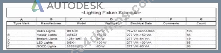
Which two actions were used to create this light fixture schedule? (Select two.)
- A. Filtered to only show lights that have a type mark value.
- B. Sorted by type mark.
- C. Deselected Itemize every instance.
- D. Sorted by instance and quantity.
- E. Added both electrical and switch system settings.
Answer: B,C
Explanation:
In the given Lighting Fixture Schedule, each row represents a lighting fixture type rather than individual instances, and the "Count" column summarizes how many fixtures of that type exist in the project. To achieve this layout in Revit, two specific actions must be performed in the Schedule Properties dialog:
Deselected "Itemize every instance."
The Revit documentation explains:
"Itemize every instance. This option displays all instances of an element in individual rows. If you clear this option, multiple instances collapse to the same row based on the sorting parameter. If you do not specify a sorting parameter, all instances collapse to one row." By deselecting this checkbox, Revit consolidates identical fixture instances of the same type into a single row - exactly as shown in the exhibit, where each "Type Mark" (A, B, C, etc.) appears once with a summarized Count.
Sorted by Type Mark.
On the same Sorting/Grouping tab, Revit allows users to organize the schedule by a specific field:
"On the Sorting/Grouping tab of the Schedule Properties dialog, you can specify sorting options for rows in a schedule... You can sort by any field in a schedule, except Count." In the example, fixtures are sorted alphabetically by their "Type Mark" (A through E). This ensures the grouped and counted results appear in order.
Other options-such as filtering by type mark or adding switch data-do not impact how instances collapse or group within the schedule.
NEW QUESTION # 26
Refer to exhibit.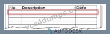
An electrical designer is issuing several sheets and wants 'Issued for Bid" to appear in the revision schedule of the title block. Drag and drop into the correct order to indicate how this can be accomplished to only the sheets that are being issued.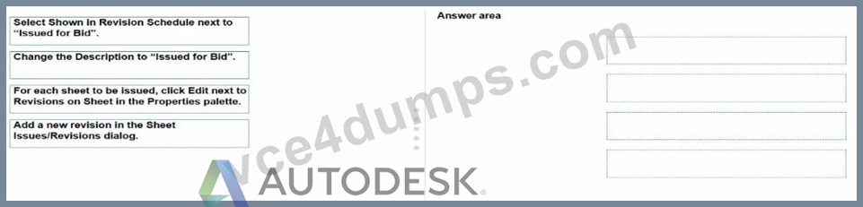
Answer:
Explanation: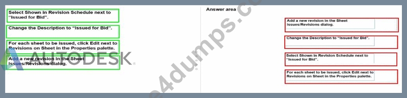
NEW QUESTION # 27
How can an arrowhead be added to a lag leader line?
- A. Select the tag and enable Leader Line in the Properties palette
- B. Choose an arrow type for the Leader Arrowhead in the Type Properties.
- C. Enable Leader Arrowhead in the instance properties.
- D. Change the Leader Type to Free End.
Answer: B
Explanation:
In Autodesk Revit for Electrical Design, arrowheads on leader lines-such as those used with tags, text notes, or annotations-are controlled through Type Properties, not through instance properties or free-end options.
According to the Revit MEP User's Guide - Annotating Chapter (Chapter 47 and 42), the section "Modifying Tags" explains:
"Select the tag, and on the Properties palette, click (Edit Type). In the Type Properties dialog, select a value for Leader Arrowhead to add an arrowhead to the leader line." This confirms that the arrowhead is defined at the type level, meaning any change applies to all tags or text notes of that annotation type throughout the project. The Leader Arrowhead property allows the designer to choose from predefined arrowhead styles (like "Filled Arrow," "Dot," "Tick Mark," etc.), which are defined globally under:
Manage tab → Settings panel → Additional Settings → Arrowheads.
Furthermore, the document specifies under "Leader Arrowhead Properties":
"Sets the arrowhead shape on the leader line. The value is the name of the arrowhead style defined by the Arrowheads tool." This behavior applies to all annotation categories, including text notes, keynotes, material tags, and electrical device tags, maintaining consistency across all view types in an electrical project.
Therefore, Option C is the correct answer because arrowheads are configured via Type Properties, while the other options are inaccurate:
Option A (Free End) only defines leader attachment behavior.
Option B (Instance properties) does not include a "Leader Arrowhead" toggle.
Option D (Enable Leader Line) only adds or removes a leader line, not the arrowhead style.
References:
Autodesk Revit MEP User's Guide - Chapter 47 "Annotating," pp. 1040-1055 Autodesk Revit MEP User's Guide - Chapter 42 "Text Notes and Tags," pp. 936-949 Autodesk Revit Electrical Design Essentials - "Leader Arrowhead Properties and Annotation Standards"
NEW QUESTION # 28
An electrical designer needs to directly connect panel B to panel A without a breaker. Panel A's load must reflect the entire load from panel B. Which conditions must be met to ensure that panel B is correctly connected to panel A?
- A. Both panels are assigned to the same switchboard, and the subfeed lug breaker option is selected.
- B. Both panels are assigned to the same distribution system, and the connection type is set to feed through lugs.
- C. Both panels are connected via a transformer, and the connection type is set to feed through lugs.
- D. Both panels are assigned to the same distribution system, and the circuit subfeed panel type option is selected.
Answer: B
Explanation:
In Autodesk Revit Electrical Design, when an electrical designer needs to directly connect Panel B to Panel A without a breaker-such that Panel A's load includes the total load from Panel B-the correct method is to configure both panels to use the same distribution system and to set Panel B's connection type to Feed Through Lugs.
According to the Autodesk Revit MEP User Guide, Chapter 17: Electrical Systems, under "Creating Power and Lighting Circuits" and "Panel Properties" sections:
"When connecting panels in series, ensure both devices share the same distribution system. If a subpanel is required to pass its total load through to another panel without circuit protection, specify the connection type as Feed Through Lugs. This connection allows the upstream panel to include the total connected load from the subpanel in its own load summary." The feed-through lugs configuration enables the second panel (Panel B) to be electrically tied to the first (Panel A) as though it were an extension of the same bus. Unlike breaker or main-lug-only setups, the feed-through configuration does not insert a protective breaker between the two panels. Instead, it provides a continuous feeder connection where the parent panel's load schedule automatically aggregates the downstream panel's total load.
This setting is found in Revit's Properties Palette for electrical equipment:
Under Electrical - Circuiting, the designer must ensure both panels use the same Distribution System (e.g., 208Y/120V 3 4W).
Then, under Connection Type, select Feed Through Lugs.
The Smithsonian Facilities Revit Template Electrical Standards Guide also confirms this best practice:
"Feed-through panels are used when a subpanel's total load must be reported in the main distribution panel without additional breakers. Both panels must share identical voltage and phase configurations within the same distribution system." Why the Other Options Are Incorrect:
A . The "subfeed lug breaker" introduces a breaker, contradicting the requirement of no breaker.
B . "Circuit subfeed panel type" is not a standard Revit configuration; Revit uses connection types instead.
D . Transformers alter the voltage distribution; the question specifies a direct connection within the same system.
Therefore, the correct configuration that meets all design and load reflection requirements is:
✅ C. Both panels are assigned to the same distribution system, and the connection type is set to feed through lugs.
References:
Autodesk Revit MEP User Guide - Chapter 17 "Electrical Systems," Sections: "Creating Power and Lighting Circuits" and "Panel Properties," pp. 420-426 Autodesk Revit Electrical Design Essentials - Topic: "Feed-Through Connections and Subpanel Load Reflection" Smithsonian Facilities Revit Template User's Guide - Section 9.3 "Panel Configuration and Feed-Through Connections," p. 96
NEW QUESTION # 29
An electrical designer Is working on a workshared model.
Which two worksharing display settings can the designer use to visualize model elements that have no ownership? (Select two.)
- A. Owners
- B. Model Updates
- C. Checkout Status
- D. Worksets
- E. Gray Inactive Worksets
Answer: A,C
Explanation:
When working in a workshared Revit model, elements without ownership can be visually identified using Worksharing Display Settings.
As per Revit MEP Worksharing Guide - Worksharing Display Modes section:
"Worksharing display modes include options such as Checkout Status, Owners, and Worksets.
The Checkout Status mode shows elements that are not owned or are available for editing.
The Owners mode highlights elements based on who owns them, allowing unowned elements to appear as 'none.'" Therefore:
✅ B. Checkout Status - shows elements that are editable or not owned.
✅ E. Owners - displays which elements are owned and highlights those without ownership.
Incorrect options:
A . Worksets: Shows which workset an element belongs to, not ownership.
C . Gray Inactive Worksets: Only grays out inactive worksets.
D . Model Updates: Not a valid worksharing display setting.
NEW QUESTION # 30
Refer to exhibit.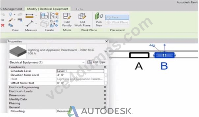
An electrical designer has accidentally hosted Panel B to Panel A. Select two ways the designer can correct hosting. (Select two.)
- A. Edit the Mounting value in the Properties palette.
- B. Edit the Host value in the Properties palette.
- C. Use the Edit Work Plane command
- D. Use the Pick New command in the Work Plane panel.
- E. Use the Move command.
Answer: C,D
Explanation:
In Autodesk Revit's Electrical discipline, when electrical components such as panelboards are hosted incorrectly (for example, Panel B hosted to Panel A instead of a wall or level), the hosting relationship must be corrected by reassigning the work plane or host. This is essential because hosted electrical elements depend on the geometry or level of their host for placement, alignment, and coordination.
According to the Revit MEP User's Guide (Chapter 45 "Work Planes and Element Hosting"):
"If a hosted element is placed incorrectly or the host has changed, use the Edit Work Plane or Pick New commands to redefine its host or work plane." Here's how these two tools apply:
Pick New (Option A)
Located under the Work Plane panel on the Modify tab, this command allows you to select a new face or host (e.g., a wall, ceiling, or floor) for the existing component. It effectively reassigns the element's host without deleting or recreating the element.
"Use Pick New to specify a different face or surface as the host for a component that was incorrectly placed."
Edit Work Plane (Option E)
This command lets the designer redefine the reference level or named work plane to which an element is associated. For hosted electrical equipment (like lighting or panels), this ensures the object references the correct structural or architectural surface.
"To correct hosting errors, open Edit Work Plane from the Modify tab, and assign a new named plane, level, or face." Incorrect Options Explanation:
B . Edit Mounting value - changes only how the panel is mounted (e.g., recessed or surface), not the host itself.
C . Move command - repositions the element but does not change the hosting relationship.
D . Edit Host value - the "Host" parameter is read-only; it cannot be edited directly.
Thus, the correct methods to rehost Panel B from Panel A to the correct wall or work plane are through Pick New and Edit Work Plane, ensuring proper association and maintaining system connectivity.
References:
Autodesk Revit MEP User's Guide - Chapter 45 "Work Planes and Hosting," pp. 1068-1072 Smithsonian Facilities Revit Template User's Guide - Section 6.2.3 "Complex Geometry and Multiple Parametric Relationships," p. 57 Autodesk Revit Electrical Design Essentials - "Rehosting Electrical Equipment and Devices"
NEW QUESTION # 31
Refer to exhibit.
(The image is presented in Imperial units: 1 In = 25 mm [Metric units rounded].)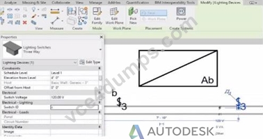
An electrical designer is trying to add the selected three-way switch to the existing switch system "b". The designer is unable to add the switch to the switch system.
Why is this problem occurring?
- A. The switch's Switch ID parameter does not match the switch system.
- B. A switch system can contain only one switch.
- C. The switch is not powered.
- D. Revit is not in Edit Switch System mode.
Answer: A
Explanation:
In Autodesk Revit Electrical Design, lighting control systems such as single-pole, three-way, and four-way switches are managed using Switch Systems. These systems logically connect lighting devices (switches) to the lighting fixtures they control. For multiple switches (like three-way configurations) to be part of the same control circuit, they must share the same Switch ID value.
In the exhibit, the electrical designer is attempting to add a three-way switch to the existing switch system labeled "b", but Revit does not allow it. The reason is that the Switch ID parameter of the new switch does not match the Switch ID of the system it is intended to join.
The Switch ID acts as the unique identifier that links all switches controlling the same group of fixtures. If the IDs differ (for example, "b3" versus "b"), Revit interprets them as belonging to separate systems and prevents them from being grouped together.
The Autodesk Revit MEP User's Guide - Electrical Systems: Lighting and Switch Systems explains this clearly:
"Switch systems are organized by Switch ID. All switches controlling the same lighting circuit must have identical Switch ID values. Revit will not allow a switch to be added to an existing system if its Switch ID does not match that system's identifier." To fix this, the designer must:
Select the three-way switch.
In the Properties palette, locate the Switch ID parameter.
Change its value to match the target switch system's ID (in this case, "b").
Once both switches share the same Switch ID, Revit will successfully include them in the same Switch System.
NEW QUESTION # 32
Refer to exhibit.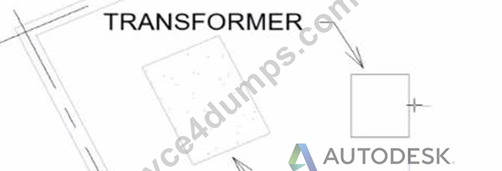
An electrical designer wants to place electrical equipment on the pad.
How should the component be aligned to the pad before placement?
- A. Place the cursor anywhere over the object and then press Spacebar.
- B. Start the Align tool. tab to select the object edge, and then select the equipment edge.
- C. Place the cursor over an edge of the object and then press Spacebar.
- D. Start the Align tool and select the edges to be aligned.
Answer: C
Explanation:
In Autodesk Revit, when placing electrical equipment such as transformers, disconnects, or switchboards onto a pad or foundation, precise alignment is essential for accurate coordination with architectural and structural elements. During component placement, Revit provides an intuitive way to align an object before final placement using the Spacebar in combination with the object's edges.
When the cursor is hovered over an edge of the component (not just anywhere on it) and the Spacebar is pressed, Revit cycles the component's orientation, rotating it 90 degrees around its insertion point each time. This technique allows the designer to visually align the equipment's orientation with the pad or architectural geometry before clicking to place it.
According to the Autodesk Revit MEP User's Guide under "Placing and Modifying Components":
"While placing a component, move the cursor over an edge and press the Spacebar to rotate the element incrementally. This method helps align electrical or mechanical equipment with nearby reference geometry before placement." This method is ideal for electrical designers positioning pad-mounted equipment, ensuring that components such as transformers or switchgear are oriented precisely to site geometry, conduit routes, or building walls.
NEW QUESTION # 33
Refer to exhibits.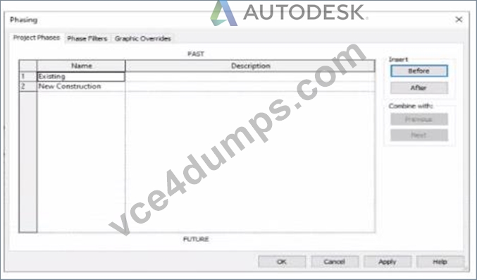
An electrical designer models an existing receptacle on an existing wall that the architect has indicated to be demolished.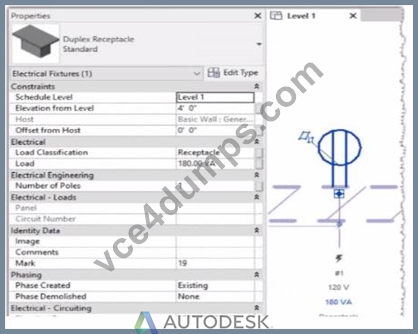
The view is intended to show demolition, and the view's Phase is set to New Construction. How should the designer indicate that the receptacle must also be demolished?
- A. Set the receptacle parameter Phase Demolished to Demolition.
- B. Add a Demolition phase, then set the receptacle parameter Phase Demolished to Demolition.
- C. Set the receptacle's type parameter Match Phasing to Host.
- D. Set the receptacle parameter Phase Demolished to New Construction.
Answer: D
Explanation:
In Autodesk Revit, phasing allows designers to track existing, demolished, and new elements across different project stages. Every model element includes two key phasing parameters:
Phase Created - defines when the element was built or introduced.
Phase Demolished - defines when the element is removed or demolished.
In the provided exhibits:
The project contains two phases: Existing and New Construction.
The receptacle's Phase Created parameter is set to Existing, indicating it belongs to the pre-existing building condition.
The architectural wall hosting the receptacle is to be demolished during New Construction.
When a view's Phase is set to New Construction and its Phase Filter is configured to show demolition, only elements whose Phase Demolished equals New Construction will appear as to be demolished. Therefore, the electrical designer must set the receptacle's Phase Demolished value to New Construction so that it graphically displays as a demolished element in the demolition plan.
As explained in the Autodesk Revit MEP User's Guide - Phasing and Coordination:
"Elements created in one phase and demolished in a subsequent phase must have their 'Phase Demolished' parameter set to that later phase to display properly in demolition views." Thus, to correctly coordinate with the demolition of its host wall, the receptacle must be flagged for demolition during New Construction.
NEW QUESTION # 34
An electrical designer wants to schedule parameters from generic annotations Which type of schedule must be created?
- A. D. A Sheet List
- B. A Generic Annotation schedule
- C. A Note Block
- D. A Generic Family schedule
Answer: C
Explanation:
When an electrical designer wants to schedule parameters from Generic Annotations, the correct method is to use a Note Block, not a generic schedule. Revit documentation defines this process clearly under Annotation Schedules (Note Blocks):
"Annotation schedules, or note blocks, list all instances of annotations that you can add using the Symbol tool."
"Creating an Annotation Schedule (Note Block):
Load the generic annotation family or families into your project and place them where desired.
Click View tab ➤ Create panel ➤ Schedules drop-down ➤ Note Block.
In the New Note Block dialog, for Family, select a generic annotation." This extract confirms that when working with generic annotation families, Revit requires the use of a Note Block to extract and list their parameters in a schedule. Standard schedules such as Generic Model or Family schedules cannot access data from Generic Annotations since they are annotation-based, not model-based.
NEW QUESTION # 35
......
Autodesk RVT_ELEC_01101 Exam Syllabus Topics:
| Topic | Details |
|---|---|
| Topic 1 |
|
| Topic 2 |
|
| Topic 3 |
|
| Topic 4 |
|
| Topic 5 |
|
Authentic Best resources for RVT_ELEC_01101 Online Practice Exam: https://www.vce4dumps.com/RVT_ELEC_01101-valid-torrent.html
Updates Up to 365 days On Developing RVT_ELEC_01101 Braindumps: https://drive.google.com/open?id=1gFVSNakdVIfgxQgRC_5rPhYMi8ae8kH6