


[2026] Pass Key features of JN0-281 Course with Updated 197 Questions
JN0-281 Sample Practice Exam Questions 2026 Updated Verified
Juniper JN0-281 Exam Syllabus Topics:
| Topic | Details |
|---|---|
| Topic 1 |
|
| Topic 2 |
|
| Topic 3 |
|
| Topic 4 |
|
| Topic 5 |
|
NEW QUESTION # 108
Which BGP message type is used to establish peering sessions?
- A. Open
- B. Notification
- C. Keepalive
- D. Update
Answer: A
NEW QUESTION # 109
What is an aggregate route?
- A. often called the route of last resort
- B. a mechanism that allows multiple routes to be summarized into a single route
- C. a group of IP addresses to which a router will not forward traffic
- D. a static route with only one contributing route
Answer: B
NEW QUESTION # 110
Which two statements are correct about VLAN tags? (Choose two.)
- A. VLAN tags can be inserted or removed by trunk interfaces.
- B. VLAN tags are required on access ports.
- C. VLAN tags carry a VLAN ID and priority.
- D. VLAN tags require multiple forwarding tables.
Answer: A,C
Explanation:
VLAN tags are used in Ethernet frames to identify and differentiate traffic between multiple VLANs. They are especially important for devices like switches that handle multiple VLANs on the same physical link.
Step-by-Step Breakdown:
VLAN Tag Contents:
VLAN ID: The tag contains a 12-bit VLAN ID field that identifies the VLAN to which the frame belongs.
Priority: The tag also includes a 3-bit priority field (also known as 802.1p priority) used for QoS (Quality of Service) to prioritize traffic.
Trunk Ports and VLAN Tagging:
Trunk Ports are used to carry traffic for multiple VLANs across a single link. These interfaces insert (tag) VLAN identifiers into frames when they leave the switch and remove (untag) them when frames enter the switch.
Access Ports:
VLAN tags are typically not used on access ports (ports that connect to end devices) since those ports are configured to be part of a single VLAN, and the traffic doesn't need VLAN tags.
Juniper Reference:
VLAN Tagging: Juniper switches support VLAN tagging and ensure that frames are tagged or untagged as they traverse trunk or access ports, respectively.
NEW QUESTION # 111
What is a VLAN?
- A. A broadcast domain, using only virtual machines
- B. A multicast domain, identified by a VLAN ID
- C. A local network using only virtual machines
- D. A broadcast domain, identified by a VLAN ID
Answer: D
NEW QUESTION # 112
How can OSPF be configured to prefer one route over another?
- A. By setting a lower cost on the preferred route.
- B. By configuring route redistribution.
- C. By setting a higher cost on the preferred route.
- D. By adjusting interface bandwidth.
Answer: A
NEW QUESTION # 113
What are two requirements for an IP fabric? (Choose two.)
- A. a Layer 2 switching protocol
- B. a Layer 3 routing protocol
- C. a single connection between each leaf
- D. a single connection between each spine and leaf
Answer: B,D
Explanation:
An IP fabric is a network architecture commonly used in data centers to provide scalable, high-throughput connectivity using a spine-leaf topology.
Step-by-Step Breakdown:
Layer 3 Routing Protocol:
An IP fabric relies on a Layer 3 routing protocol, typically BGP or OSPF, to provide routing between the leaf and spine switches. This ensures efficient traffic forwarding across the network.
Single Connection Between Spine and Leaf:
In an IP fabric, each leaf switch connects to every spine switch with a single connection. This ensures that traffic between any two leaf switches can travel through the spine layer in just two hops.
Juniper Reference:
Spine-Leaf Design: Juniper's IP fabric implementations are designed for scalability and low-latency routing, often using protocols like BGP for Layer 3 control.
NEW QUESTION # 114
When configuring static routes, which command is typically used?
- A. set routing-options rib-groups
- B. set protocols static route
- C. set route aggregate
- D. set firewall filter
Answer: B
NEW QUESTION # 115
A switch receives a frame with a MAC address of FF-FF-FF-FF-FF-FF.
Which action will the switch take on this frame?
- A. It will flood it out of all interfaces.
- B. It will flood it out of all interfaces, except for the directly connected VLAN.
- C. It will flood it out of all interfaces, except for the next-hop interface.
- D. It will flood it out of all interfaces, except for the ingress interface.
Answer: D
Explanation:
A MAC address of FF-FF-FF-FF-FF-FF is the Ethernet broadcast address. When a switch receives a frame with this destination MAC address, it is required to forward the frame to all interfaces except the one it was received on.
Step-by-Step Breakdown: Broadcast Frame Handling:
When a frame with the broadcast MAC address is received, the switch will flood it out of all active ports that belong to the same VLAN as the incoming frame. The broadcast frame is not sent back out of the ingress interface (the interface where the frame was originally received).
Purpose of Flooding:
Broadcasting is used to ensure that the frame reaches all devices within the broadcast domain (all devices within the same VLAN), which may not have a specific entry for the MAC address in their MAC address table.
Juniper
Reference: Layer 2 Frame Forwarding: Juniper switches flood broadcast frames to all ports in the same VLAN, except the port the frame was received on.
NEW QUESTION # 116
Which statement is correct about aggregate routes?
- A. The default next hop is reject.
- B. The default next hop is discard.
- C. The default next hop is resolve.
- D. The default next hop is readvertise.
Answer: A
Explanation:
An aggregate route is a summarized route that is created by combining multiple specific routes into a single, broader route. In Junos OS, when an aggregate route is configured, its default next hop is set to reject.
Step-by-Step Explanation:
Aggregate Route:
Aggregate routes are used to reduce the size of routing tables by representing a collection of more specific routes with a single summary route. They help improve routing efficiency and scalability, especially in large networks.
Default Next Hop Behavior:
When you configure an aggregate route in Junos OS, it has a reject next hop by default.
The reject next hop means that if a packet matches the aggregate route but there is no more specific route in the routing table for that destination, the packet will be discarded, and an ICMP "destination unreachable" message is sent to the source.
This behavior helps to prevent routing loops and ensures that traffic isn't forwarded to destinations for which there is no valid route.
Modifying Next Hop:
If needed, the next hop behavior of an aggregate route can be changed to discard (which silently drops the packet) or to another specific next hop. However, by default, the next hop is set to reject.
Juniper Reference:
Junos Command: set routing-options aggregate route <route> reject to configure an aggregate route with a reject next hop.
Verification: Use show route to verify the presence and behavior of aggregate routes.
NEW QUESTION # 117
BGP is primarily used for which purpose in a network?
- A. Encrypting data traffic between networks
- B. Providing Layer 2 connectivity
- C. Connecting different autonomous systems and route sharing
- D. Internal routing within a single autonomous system
Answer: C
NEW QUESTION # 118
Exhibit: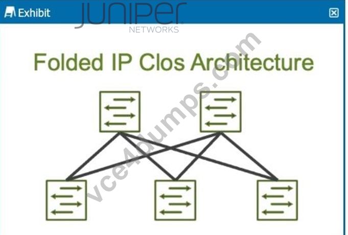
How many stages are shown in the exhibit?
- A. 0
- B. 1
- C. 2
- D. 3
Answer: B
Explanation:
The exhibit shows a Folded IP Clos Architecture, which is also referred to as a 3-stage Clos network design. This architecture typically consists of two layers of switches:
Spine Layer: The top row of switches.
Leaf Layer: The bottom row of switches.
Step-by-Step Breakdown:
Clos Architecture:
A 3-stage Clos network has two types of devices: spine and leaf. In this design, each leaf switch connects to every spine switch, providing a high level of redundancy and load balancing.
Stage Explanation:
Stage 1: The first set of leaf switches.
Stage 2: The spine switches.
Stage 3: The second set of leaf switches.
The Folded Clos architecture shown here effectively "folds" the 3-stage design by combining the ingress and egress leaf layers into one, reducing it to two visible layers, but still maintaining the overall 3-stage architecture.
Juniper Reference:
IP Clos Architecture: The 3-stage Clos design is commonly used in modern data centers for high availability, redundancy, and scalability.
NEW QUESTION # 119
Which Junos operational mode command is used to troubleshoot issues with VLANs?
- A. monitor traffic
- B. show ethernet-switching table
- C. show vlans
- D. show interfaces
Answer: B
NEW QUESTION # 120
You want to enable a Junos device to support aggregated Ethernet interfaces. In this scenario, which configuration hierarchy would you use?
- A. [edit switch-options]
- B. [edit system]
- C. [edit chassis]
- D. [edit interfaces]
Answer: C
Explanation:
To configure aggregated Ethernet (AE) interfaces on a Junos device, the configuration is done under the [edit chassis] hierarchy.
Step-by-Step Breakdown:
Chassis Configuration:
The chassis configuration is responsible for enabling the hardware to support Link Aggregation Groups (LAGs), allowing multiple physical interfaces to be bundled into a single logical interface for load balancing and redundancy.
Command Example:
set chassis aggregated-devices ethernet device-count <number>
This command enables a specific number of aggregated Ethernet interfaces on the device.
Juniper Reference:
LAG Configuration in Junos: The chassis hierarchy is used to allocate and manage hardware resources for aggregated Ethernet interfaces in Juniper devices.
NEW QUESTION # 121
Which of the following is an important consideration when configuring BFD?
- A. Adjusting the BFD interval and multiplier according to network needs
- B. Using the same BFD interval on all devices in the network
- C. Setting a very high multiplier to avoid false positives
- D. Disabling all other failure detection mechanisms
Answer: A
NEW QUESTION # 122
Which statement is correct about the BGP AS path when advertising routes?
- A. The order of the AS path is only significant in IBGP.
- B. The local AS number is added to the end of the AS path.
- C. The order of the AS path is not significant.
- D. The local AS number is added to the beginning of the AS path.
Answer: D
Explanation:
The BGP AS (Autonomous System) path attribute is crucial in path selection and loop prevention.
Each BGP router appends its local AS number to the beginning of the AS path when it advertises a route to an external BGP (eBGP) peer.
Step-by-Step Breakdown:
AS Path Attribute:
The AS path is a sequence of AS numbers that a route has traversed to reach a destination. Each AS adds its number to the front of the path, allowing BGP to track the route's history.
Why the Local AS is Added at the Beginning:
When advertising a route to an eBGP neighbor, a BGP router adds its own AS number to the beginning of the AS path. This ensures that the AS path reflects the route's journey accurately from the origin to the destination, and prevents loops in BGP. If the route returns to the same AS, the router will detect its AS number in the path and reject the route, preventing routing loops. Order of the AS Path:
The order is significant because BGP uses it to select the best path. A shorter AS path is preferred, as it indicates fewer hops between the source and destination. Juniper Reference: AS Path Attribute: Junos devices append the local AS at the start of the AS path before advertising the route to an external peer.
NEW QUESTION # 123
VLANs help in reducing which of the following? (Choose two)
- A. Collision domains
- B. Routing complexity
- C. Encryption requirements
- D. Broadcast domains
Answer: A,D
NEW QUESTION # 124
Which of the following BGP attributes is considered first in the route selection process?
- A. MED
- B. AS Path Length
- C. Origin
- D. Local Preference
Answer: D
NEW QUESTION # 125
Which statement is correct about member interfaces when creating a LAG?
- A. Member interfaces must all be allocated on the same PFE.
- B. The interface's duplex settings and link speed must be the same on all member interfaces.
- C. The interface's MTU settings must match on all member interfaces.
- D. Member interfaces must all be allocated on the same chassis when using a Virtual Chassis.
Answer: B
Explanation:
When creating a LAG (Link Aggregation Group) in Junos, the duplex settings and link speed must be the same across all member interfaces.
Step-by-Step Breakdown:
LAG Overview:
A LAG combines multiple physical interfaces into a single logical interface to increase bandwidth and provide redundancy. All member links must act as a single cohesive unit.
Interface Requirements:
Duplex: All member interfaces must operate in the same duplex mode (either full-duplex or half-duplex). Mismatched duplex settings can cause performance issues, packet drops, or interface errors.
Link Speed: All interfaces in the LAG must have the same link speed (e.g., all interfaces must be 1 Gbps or 10 Gbps). Mismatched speeds would prevent the interfaces from functioning correctly within the LAG.
Configuration and Validation: Ensure that all member interfaces have identical settings before adding them to the LAG. These settings can be checked using the show interfaces command, and the LAG can be configured using:
set interfaces ae0 aggregated-ether-options link-speed 10g
set interfaces ge-0/0/1 ether-options 802.3ad ae0
Juniper Reference:
LAG Configuration: Duplex and link speed must be consistent across member interfaces to ensure proper LAG operation in Juniper devices.
NEW QUESTION # 126
When troubleshooting an OSPF neighborship, you notice that the router stopped at the ExStart state.
What is the cause of this result?
- A. There is an MTU mismatch.
- B. There is an area ID mismatch.
- C. The priority is set to 255.
- D. There is an interval timing mismatch.
Answer: A
Explanation:
When an OSPF (Open Shortest Path First) neighborship is stuck in the ExStart state, it usually points to a mismatch in Maximum Transmission Unit (MTU) settings between two routers trying to establish the adjacency. The ExStart state is where OSPF routers negotiate the master-slave relationship and exchange DBD (Database Description) packets.
Step-by-Step Breakdown:
OSPF Neighbor States: OSPF goes through several states to establish an adjacency with a neighbor:
Down: No hello packets have been received.
Init: Hello packets are received, but bidirectional communication isn't confirmed.
2-Way: Bidirectional communication is established.
ExStart: The routers are negotiating who will be the master and who will be the slave, and begin to exchange DBD packets.
Exchange: The routers start exchanging the database information.
Loading: The routers process the Link-State Advertisements (LSAs).
Full: The adjacency is fully established.
MTU Mismatch Issue:
During the ExStart state, both OSPF routers must agree on their MTU values. If there is an MTU mismatch between the two routers, OSPF neighbors will fail to move from the ExStart to the Exchange state. The router with the larger MTU setting will not accept DBD packets from the router with a smaller MTU because the packets may exceed the smaller MTU size.
In Juniper devices, this behavior can be identified by examining the MTU settings using the show interfaces command and ensuring both routers have matching MTU configurations. To resolve this issue, either match the MTU settings on both routers or configure OSPF to ignore MTU mismatches using the command set protocols ospf ignore-mtu.
Juniper
Reference: Junos Command: show ospf neighbor helps diagnose neighbor states.
MTU Adjustment: set interfaces <interface-name> mtu <size> can be used to set the MTU values correctly.
NEW QUESTION # 127
Exhibit: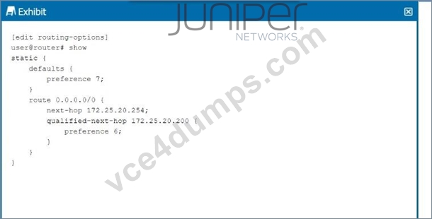
Referring to the exhibit, which next hop will be preferred in the routing table?
- A. Next hop IP address 172.25.20.254 will be preferred.
- B. Next hop IP address 172.25.20.200 will be preferred.
- C. Neither next hop will be preferred.
- D. Both next hops will be preferred.
Answer: B
Explanation:
In the exhibit, we see a static route configuration with two possible next hops for the default route (0.0.0.0/0):
next-hop 172.25.20.254 with the default preference of 7.
qualified-next-hop 172.25.20.200 with a preference of 6.
Step-by-Step Breakdown:
Preference Value:
In Junos OS, the preference value is used to determine which route should be preferred in the routing table. The lower the preference value, the higher the priority for the route.
Comparison:
In this case:
The next hop 172.25.20.254 has a preference of 7.
The qualified-next-hop 172.25.20.200 has a preference of 6.
Preferred Next Hop:
Since 172.25.20.200 has a lower preference (6) compared to 172.25.20.254 (7), it will be the preferred next hop in the routing table, assuming both next hops are reachable.
Juniper Reference:
Qualified Next Hop: In Junos, static routes with multiple next-hop options are selected based on the preference value, with the lower value being preferred.
NEW QUESTION # 128
In the Junos OS, which feature is used to create an alternate next hop with a unique preference for a static route?
- A. Preference
- B. Qualified-next-hop
- C. Resolve
- D. Next-hop
Answer: B
Explanation:
In Junos OS, the qualified-next-hop feature is used to specify an alternate next hop for a static route, along with a unique preference value.
Step-by-Step Breakdown:
Qualified-Next-Hop:
A qualified-next-hop allows you to define multiple next hops for a static route, each with its own preference. This provides flexibility by allowing the router to choose the best available next hop based on reachability and preference.
Use Case:
If the primary next hop becomes unreachable, the router can automatically switch to the alternate next hop defined by the qualified-next-hop with a higher preference value.
Command Example:
set routing-options static route 10.10.10.0/24 qualified-next-hop 192.168.1.1 preference 5 set routing-options static route 10.10.10.0/24 qualified-next-hop 192.168.1.2 preference 10 Preference:
The next hop with the lowest preference is chosen first. If it becomes unavailable, the router will use the higher preference next hop.
Juniper
Reference: Qualified-Next-Hop: This feature is used to configure backup or alternate next hops for static routes in Juniper devices.
NEW QUESTION # 129
Leaf and spine data centers are used to better accommodate which type of traffic?
- A. south-east
- B. east-west
- C. north-west
- D. north-east
Answer: B
Explanation:
In modern data centers, the shift toward leaf-spine architectures is driven by the need to handle increased east-west traffic, which is traffic between servers within the same data center. Unlike traditional hierarchical data center designs, where most traffic was "north-south" (between users and servers), modern applications often involve server-to-server communication (east-west) to enable services like distributed databases, microservices, and virtualized workloads. Leaf-Spine Architecture:
Leaf Layer: This layer consists of switches that connect directly to servers or end-host devices. These switches serve as the access layer.
Spine Layer: The spine layer comprises high-performance switches that provide interconnectivity between leaf switches. Each leaf switch connects to every spine switch, creating a non-blocking fabric that optimizes traffic flow within the data center.
East-West Traffic Accommodation:
In traditional three-tier architectures (core, aggregation, access), traffic had to traverse multiple layers, leading to bottlenecks when servers communicated with each other. Leaf-spine architectures address this by creating multiple equal-cost paths between leaf switches and the spine. Since each leaf switch connects directly to every spine switch, the architecture facilitates quick, low-latency communication between servers, which is essential for east-west traffic flows. Juniper's Role:
Juniper Networks provides a range of solutions that optimize for east-west traffic in a leaf-spine architecture, notably through:
QFX Series Switches: Juniper's QFX series switches are designed for the leaf and spine architecture, delivering high throughput, low latency, and scalability to accommodate the traffic demands of modern data centers.
EVPN-VXLAN: Juniper uses EVPN-VXLAN to create a scalable Layer 2 and Layer 3 overlay network across the data center. This overlay helps enhance east-west traffic performance by enabling network segmentation and workload mobility across the entire fabric.
Key Features That Support East-West Traffic:
Equal-Cost Multipath (ECMP): ECMP enables the use of multiple paths between leaf and spine switches, balancing the traffic and preventing any one path from becoming a bottleneck. This is crucial in handling the high volume of east-west traffic.
Low Latency: Spine switches are typically high-performance devices that minimize the delay between leaf switches, which improves the efficiency of server-to-server communications.
Scalability: As the demand for east-west traffic grows, adding more leaf and spine switches is straightforward, maintaining consistent performance without redesigning the entire network. In summary, the leaf-spine architecture is primarily designed to handle the increase in east-west traffic within data centers, and Juniper provides robust solutions to enable this architecture through its switch platforms and software solutions like EVPN-VXLAN.
NEW QUESTION # 130
......
The New JN0-281 2026 Updated Verified Study Guides & Best Courses: https://www.vce4dumps.com/JN0-281-valid-torrent.html
Exam Study Guide Free Practice Test LAST UPDATED : https://drive.google.com/open?id=1Z9eV_6fx_ou7Uch1W9LZ-S-JvUkifa7g